Loading... Please wait...
- Home
- Electronic Design Blog
- Color Sensor to RGB LED Driver with an Arduino
Color Sensor to RGB LED Driver with an Arduino
Posted by Lon Glazner on 14th Aug 2018
I’m in the process of adding the BM017 Color Sensor to our web site. This breakout module is based on the TCS34725 by AMS (formerly Taos). You can use it to detect red, green, blue, and clear color values from object in front of the sensor. I covered basic use of the sensor in my post Sensing Color with the Arduino and the TCS34725. The code I use here builds on that blog post.
I was interested in writing some Arduino code that would use the BM017 to sense colors and then use the readings to drive an RGB LED. The goal was to place a color in front of the sensor and have the RGB LED turn the same color. It turns out this is pretty easy to do, but there are a couple of “gotchas”.
 Since the BM017 provides red, green, and blue (RGB) color components of the
object in its field of view it makes sense that you can use the ratio of the
color sensor readings to drive an RGB LED to match the object’s color. I took a
colorimetry class in college (back when dinosaurs roamed the earth). From what
I recall color measurements are complicated things. I was hoping to avoid
things like considerations of color temperature, luminescence, and any need for
special chromatic instrumentation. After all, this was supposed to be a couple
of hours of messing around in the lab.
Since the BM017 provides red, green, and blue (RGB) color components of the
object in its field of view it makes sense that you can use the ratio of the
color sensor readings to drive an RGB LED to match the object’s color. I took a
colorimetry class in college (back when dinosaurs roamed the earth). From what
I recall color measurements are complicated things. I was hoping to avoid
things like considerations of color temperature, luminescence, and any need for
special chromatic instrumentation. After all, this was supposed to be a couple
of hours of messing around in the lab.
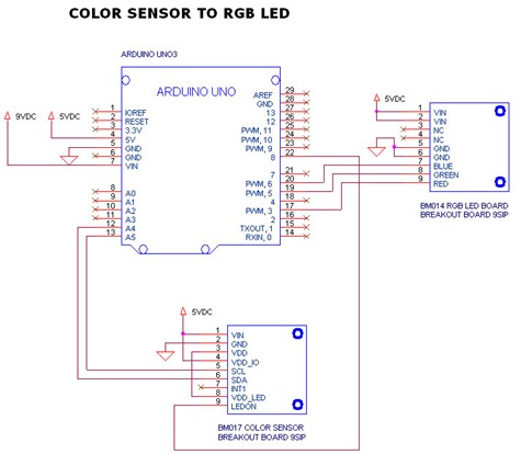
I used an Arduino Uno to get data from the color sensor, then generated 3 PWM signals in the Arduino to drive a high current RGB LED. The schematic is above. Here are a few things I figured out during the project.
Output: Not all RGB LEDs are the same, so you may have to adjust the program based on yours. Each LED in the RGB package has a different forward voltage. Each LED also has a different current rating for its highest brightness. For example, in my RGB LED red peaked at 140mA, green at 160mA, and blue at 125mA. I powered my RGB LED off of 5V and used different resistor values for each color component of the LED. My goal was to have 100% duty cycle for each LED color be the highest brightness point for that color. If each color component was equal I would have an output that was white. This is is not what I saw in the lab with my initial hardware setup. With all PWM outputs equal my white was more like a yellow. I could modify resistor values. After some experimentation I determined there was too much green. I used a scaling factor (variables “redintensity”, “greenintensity”, “blueintensity”) to reduce the amount of green as compared to red and blue. This could also be done in hardware by increasing the resistor value on the green LED.
I also noted that at drive signals below ~50% the RGB LED I was using appeared to strobe. This was interesting, because the PWM signal’s period was too fast to cause the strobe. I think the blue and green LEDs were “dropping out” at lower duty cycles due to higher forward voltages. I used the intensity variables to keep the PWM signals higher.
Lastly, a word of caution. For my experiment I used a high brightness “true blue” RGB LED. This LED can draw 400+ mA. It is so bright that it hurts your eyes to look at it. Seriously, I left it uncovered and just a couple of glances at it had my eyes aching. I had to cover it with a frosted glass candle holder. This helped diffuse the color being generated as well as saving me from blindness.
The code below was what I used in the Arduino to convert color readings to
PWM signals to drive the RGB LED.
Here are links for the source code
discussed in this blog.
BM017_Arduino_color_sensing.zip
- Arduino Uno3 code example for basic red, green, and blue color sensing.
BM017_Arduino_RGB_LED_driver.zip
- Arduino Uno3 code example reading color and converting it to RGB LED drive
signals.
void drive_LEDs(void)
{
// intensity” floating point registers can be
// used to adjust for LEDs of different intensity.
// Equal r, g, and b values should output a
// white light.
redintensity = 2; //
greenintensity = 1.8; //
blueintensity = 2; //
// Normalized value * intensity adjustment
rednorm = rednorm*redintensity;
greennorm = greennorm*greenintensity;
bluenorm = bluenorm*blueintensity;
// Convert value to PWM drive
rednorm = rednorm*255;
greennorm = greennorm*255;
bluenorm = bluenorm*255;
// Make sure to limit values to max PWM
if (rednorm > 255)
rednorm = 255;
if (greennorm > 255)
greennorm = 255;
if (bluenorm > 255)
bluenorm = 255;
// Output PWM values
analogWrite(redPin,(int)(rednorm));
analogWrite(greenPin,(int)(greennorm));
analogWrite(bluePin,(int)(bluenorm));
// send register values to the serial monitor
Serial.print("r=");
Serial.print((int)(rednorm), DEC);
Serial.print(" g=");
Serial.print((int)(greennorm), DEC);
Serial.print(" b=");
Serial.println((int)(bluenorm), DEC);
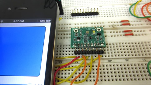
}Input: I’ve covered the I2C communication with the TCS34725 in my previous blog (linked above). That blog shows how to reads data from the sensor using I2C. I still had to figure out what I was going to put in front of the color sensor, and I had a couple of options. I first tried turning on the the white illumination LED on the BM017 and measuring colors off of colored cards I made from things around the office. This kind of worked, but I didn’t have a wide range of colors I could test.
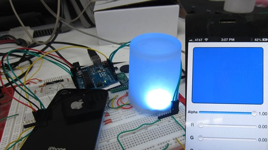
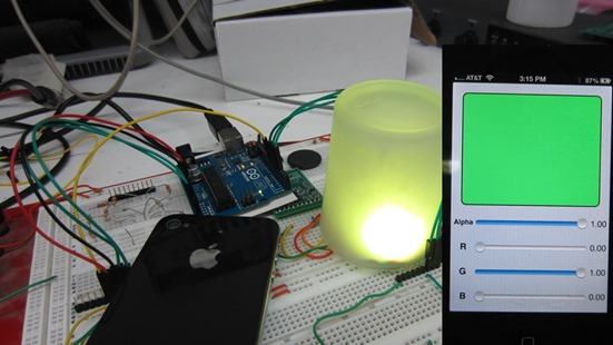
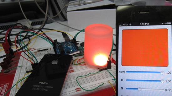
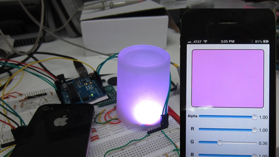
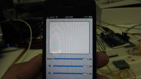 Eventually I downloaded an RGB app for my iPhone. This allowed me to
experiment with a variety of colors and know what the R, G, and B ratios were
for the colors I was testing. There was an added benefit of the iPhone screen
providing its own illumination for the sensor.
Eventually I downloaded an RGB app for my iPhone. This allowed me to
experiment with a variety of colors and know what the R, G, and B ratios were
for the colors I was testing. There was an added benefit of the iPhone screen
providing its own illumination for the sensor.
Initially I normalized the color values by creating a percentage of the color value relative to the maximum integration value possible. For example, with my settings the highest color value could be 10240. Unfortunately, even with the gain set high, I was only getting to about 30% of the peak value. I then tried using the “clear” color value as my peak value, and this seemed to do the trick. The clear color measurement gives a good indication of the maximum color value for the R, G, and B readings.
/*
Reads the register values for clear, red, green, and blue.
*/
void get_Colors(void)
{
  unsigned int clear_color = 0;
  unsigned int red_color = 0;
  unsigned int green_color = 0;
  unsigned int blue_color = 0;

// read the color registers
  Readi2cRegisters(8,ColorAddress);
  clear_color = (unsigned int)(i2cReadBuffer[1]<<8) + (unsigned int)i2cReadBuffer[0];
  red_color = (unsigned int)(i2cReadBuffer[3]<<8) + (unsigned int)i2cReadBuffer[2];
  green_color = (unsigned int)(i2cReadBuffer[5]<<8) + (unsigned int)i2cReadBuffer[4];
  blue_color = (unsigned int)(i2cReadBuffer[7]<<8) + (unsigned int)i2cReadBuffer[6];

// normalize the colors
  rednorm = (float)red_color/(float)clear_color;
  greennorm = (float)green_color/(float)clear_color;
  bluenorm = (float)blue_color/(float)clear_color;

}
You can down load the entire Arduino code from our web site on the BM017 page or on our application notes page.
Here were some of the results from the various color matching attempts.